Lab 6: Operating Fixed Wing UAS
Introduction:
There are many reasons why operating a fixed wing UAS is advantageous over a multi-rotor UAS. A multi-rotor UAS is designed much like a helicopter, while a fixed wing UAS is designed much like a fixed wing aircraft. Until UAS were developed, fixed wing aircraft was used to acquire imagery for almost all surveying purposes. Therefore, the fixed wing UAS design is becoming more common for UAS surveying applications. Using a fixed wing UAS can allow a surveyor to map a much larger area over a shorter amount of time. Also, fixed wing UAS are generally much more durable than a multi-rotor UAS and can cover heavier amounts of payload. Therefore, more mapping is able to be accomplished more efficiently, with heavier, more expensive payloads, which saves the organization money. The fixed wing UAS used in this study area was the Trimble UX5 - HP (Figure 1). This UAS is one of the most durable UAS's in the fleet. It requires a launcher and a flat area of at least 20 - 30 meters to successfully land.

Figure 1. Trimble UX 5 - HP UAS
Objectives:
- Establish ground control to orthorectify imagery to a higher degree of accuracy
- Fly Trimble UX5 - HP to collect RGB imagery of the quarry
- Post - process imagery to create DSM, point cloud and orthomosaic that can be used as inputs to estimate volumetric change within the quarry
Study Area:

Figure 2. Study Area - La Crescent Rock Products Inc.
- La Crescent Rock Products Inc. ~ La Crescent, MN
- The site was originally covered by forest. In the late 1980's the land cover was used for agricultural practices, however in the early to late 2000's the land was covered to a quarry for stockpiling rocks and minerals. Blasts are frequent throughout the quarry to modify the landscape.
- Total area covered ~ 80 acres
Workflow:
Data Acquisition:
- 8 GCPs were placed uniformly throughout the outside edges of the quarry
- GCP position were collected using Trimble RTK unit
- GCPs were made from fabric held in position by stakes directly over UWL survey monuments
- Trimble UX 5 - HP UAS does not enable manual flight. Therefore, a highly detailed flight plan is needed to be made using the Trimble flight planning software on the Yuma 2 tablet.
- Flight planning information is listed below (Figure 3)

(Figure 3. Trimble UX 5 - HP mission)
- Some highlights include:
- 120 meter flying height
- 70 % overlap
- 359 images collected
- 25 minute flight time
- Trimble UX5 - HP is sent on flight to collect imagery
Processing:
- Load images into Pix4D Mapper
- Import the projected coordinate system used for collecting GCPs (Figure 4)

(Figure 4. Output coordinate system used to orthorectify GCPs and georeference images)
- Import GCPs into GCP editor page. GCPs will show up in project page (Figure 5)

(Figure 5. GCPs within project page)
- Select GCP points within GCP Manager page (Figure 6 & Figure 7)
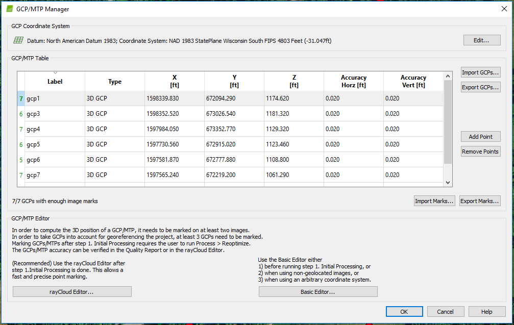
(Figure 6. GCP manager)

(Figure 7. GCP selection)
- Process data to create Orthomosaic, Point Cloud, and DSM
Results:
- 348 out of 356 images calibrated (97%)
- 7 GCPs (7 3D), mean RMS error = 0.024 ft
- 79.52% relative difference between initial and optimized internal camera parameters
October inaccuracy ~
2D
15 cm =
5.90551 in. = 0.492126 ft. = 0.149999954 m.
3D
October DSM elevation = 1061.661743 ft.
GCP elevation = 1061.29ft
Inaccuracy: 0.371743 ft. ~ 4.460916 in ~ 0.1133072664 m. ~ 11.33072664 cm.

(Figure 8. Spatial overlap of images)

(Figure 9. GCP and manual tie point accuracy)

(Figure 10. 2D keypoint matches)
Point Cloud, DSM, Orthomosaic Details

(Figure 11. Point cloud details)

(Figure 12. DSM and Orthomosaic details)
Outputs:

(Figure 13. DSM Map)

(Figure 14. Orthomosaic Map)
Conclusion:
In conclusion, our outputs are able to be used for volumetric change estimation. With installation of survey monuments we are able to place GCPs over their exact original location. Doing this provides high locational accuracy between surveys. The DSM allows us to calculate volume of various stockpiles throughout the quarry and/or for the entire quarry, and compare where resources have been lost or gained within the quarry between later surveys.