Lab 5: GCP Correction
By: Jack Radenz
Introduction:
Ground Control points commonly known as GCPs enable a large increase of accuracy for UAS surveys. GCPs are points of a known location of high accuracy that can be identified in UAS acquired imagery. During the post-processing portion of a UAS survey, these GCPs can be georeferenced from the orthomosaic and used as keypoints when the image is being orthorectified. The use of GCPs can increase the accuracy of an overall survey from 2-3 meters to 2- 3 centimeters in the horizontal domain.
Study Area:
Myrick Park: La Crosse, Wisconsin
43°49'22.02"N
91°13'30.62"W

Figure 1. Study area (Myrick Park, La Crosse, WI)
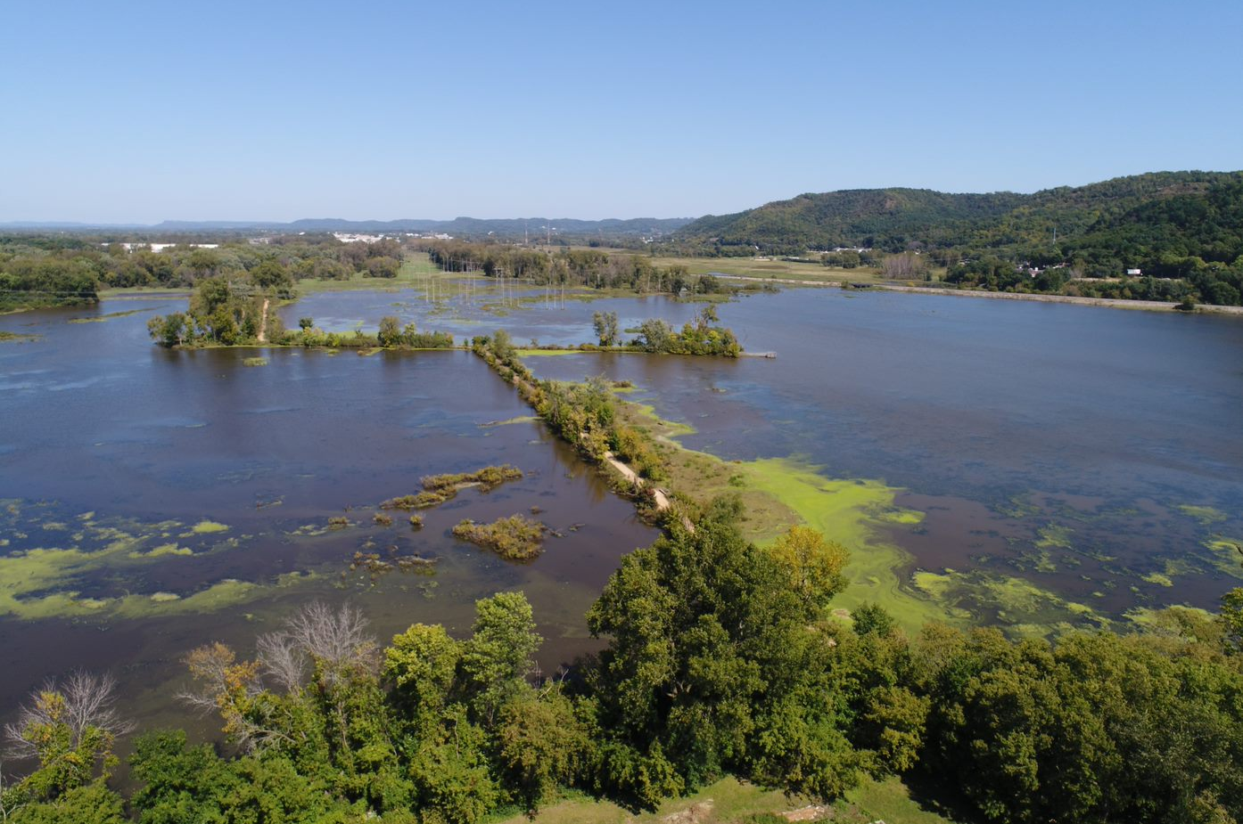
Figure 2. (below)

Figure 3 & 4. Oblique image captured by UAS of study area
Data was collected near the gun shelter located in the city of La Crosse at Myrick Park. Myrick Park was home to an old shooting range. It was not until the 1960's that Myrick Park was designated as a preserve and become submergent wetlands. When large rain events happen within the city of La Crosse, these wetlands are a 'sponge' that prevents large amounts of flooding. When the Mississippi and La Crosse River are running at high water level marks after large rain events, they are able to distribute some of their flow here so the city (which mostly sits on a flood plain) does not become overflown. Possible obstacles located within the study area are low lying powerlines, guy wires, eagles/hawks, and helicopters flying to Gunderson Hospital and low altitudes. This study area provides us with an otherwise very open area to be flow with trees reaching a maximum height of 30 - 40 feet. The land below consists of marshland/submergent wetland (70 - 80 % water, 20 - 30 % land). Water is contaminated with lead (bullets) from past land use.
Installation of GCPs:
GCPs look much like targets (Figure 5). Every GCP needs a point in the middle of the target that can be identified from the imagery. With a higher resolute imagery, the finer the crosshairs in the middle of the target will need to be.


Figure 5. Variety of ground control points
To establish permanent control a 4 foot long piece of re-bar will need to be pounded into the ground. On top of the re-bar will sit a brass cap. Once the location is taken at this point, this will become a fixed point and will not move throughout time. Therefore, once location is taken once, it can be assumed for the entirety of the surveys. For this survey, there was no permanent installation of GCPs.
- First, determine where ideal distribution of GCPs exists throughout the survey. GCPs should be uniformly distributed throughout the study area. No clustering of GCPs should exist.
- Second, stake GCP to the ground. Make sure the GCP will not move due to environmental conditions. Also, ensure GCP is able to be seen from UAS. Canopy cover or shadow should not exist over any GCP.
- Third, record GCP location using GPS (Figure 6)

Figure 6. GCP locational recording using Geo XH 6000 GPS
- Fourth, if able, fly over study area using UAS streamed video to examine distribution of GCPs across space

Figure 7. Flight parameters of GCP flight
- The coordinates of each GCP location will be saved into a txt. file similar to the one listed below. Our GCP file has GCP#, northing and easting coordinates, and geoid coordinates (values for the vertical domain) (Figure 4)
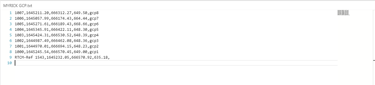
Figure 8. GCP text file
Post Processing:
GCP locations can now be incorporated into the UAS survey through Pix4D.
- First, the text file is loaded into the program through clicking 'import GCPs'
- Second, the GCP locations will appear on the project interface screen (Figure 9)

Figure 9. GCP locations within Pix4D
- Third, each GCP will need to be tagged within 5 - 6 images throughout the project (Figure 10)

Figure 10. Tagging GCPs within images
- After GCPs are tagged in 5 - 6 images, the surveyor can close the GCP screen and begin processing.
Project Report:
A project report is a great way of identifying how well your images collected during the survey were processed. If errors occurred, it is important to account for them and adjust the study accordingly. Here is the report for the outputs created through Pix4D.
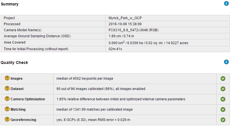
Figure 11. Project Report (details resolution (GSD), area covered, number of keypoints, etc.)

Figure 12. Project Report ( details number of keypoints found. Large amount of keypoints signify a large amount of accuracy)
Uncorrected and Corrected GCP:
The post processing capabilities of using differential correction can improve accuracy from 3 - 5 meters to 2 - 3 cm. This change can be seen from the map shown below (Figure 13). The red marks are the corrected GCP locations and the yellow marks are uncorrected GCP locations. The red marks can be seen correctly located in the center of the GCPs. No only is it important to incorporate GCPs into a UAS survey, but it is also just as important to use differential correction or real time correction techniques while collecting GPS data at each GCP.

Figure 13. Uncorrected and corrected GCP points at Myrick Park, La Crosse, WI
Orthomosaic:
The GIF below illustrates the locational shift that occurs when GCPs are absent from a project and when GCPs are applied during a project. Therefore, when GCPs are not incorporated into the post processing the orthomosaic is much less accurate than the orthomosaic that had incorporated GCPs. The orthomosaic is put on a much more accurate location on the surface of the earth when GCPs are used.

Figure 14. Orthomosaic shift from higher achieved accuracy due to GCP installation. (First image w/out GCP, second image w/ GCP)